
 Toolbox
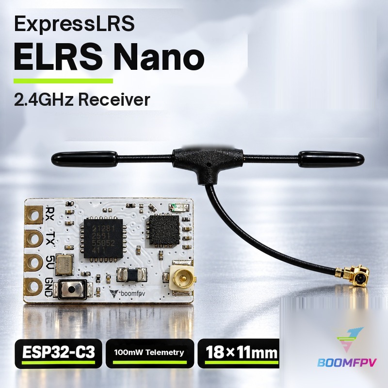
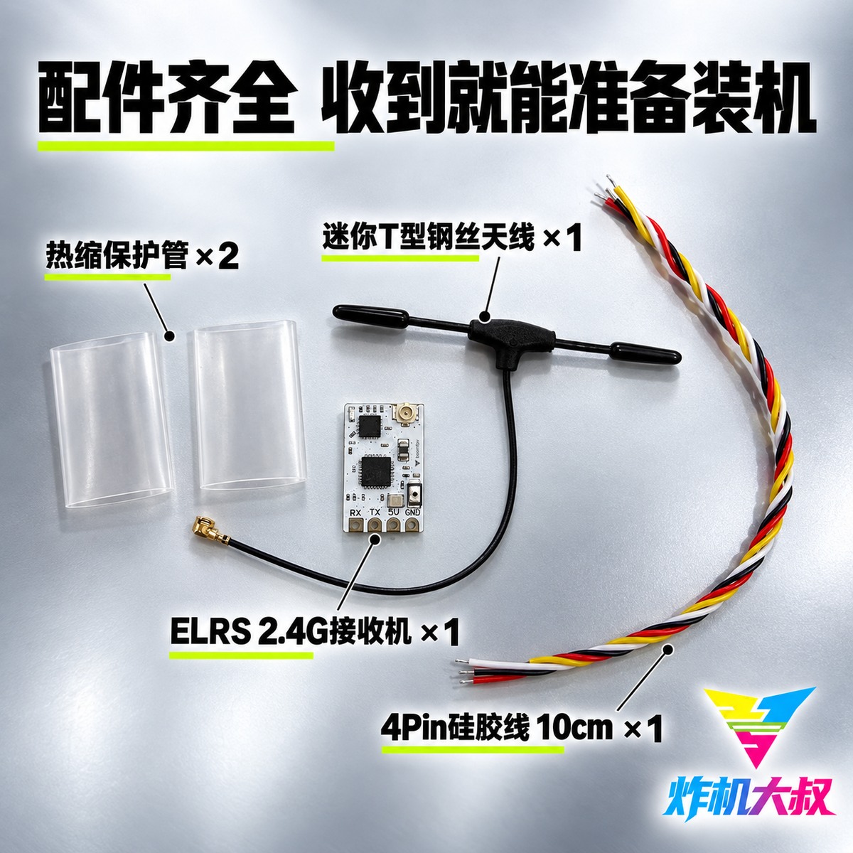
ELRS Nano 2.4G receiver overview
An ELRS Nano 2.4G receiver on a white PCB with ESP32-C3 and SX1281, offered in-house by BOOMFPV(炸机大叔).
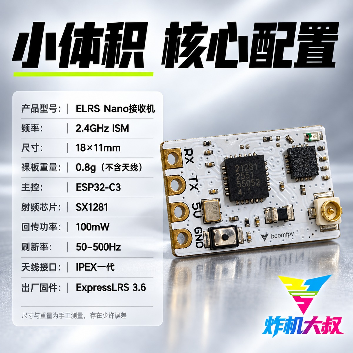
Hardware specifications
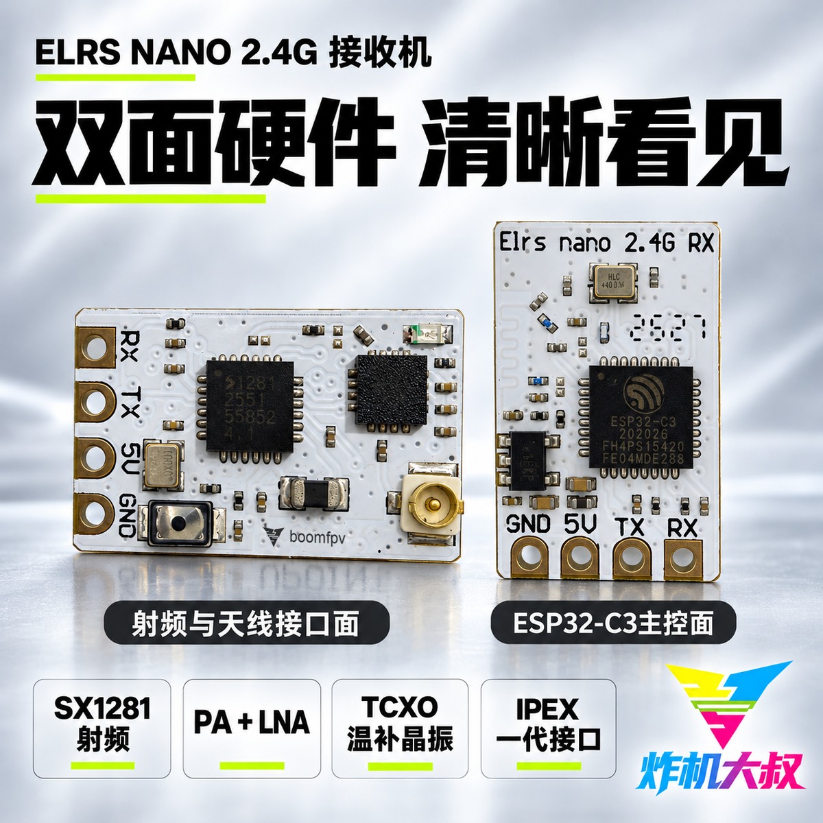
2.4GHz ISM, 18×11mm, bare board 0.8g (antenna not included); ESP32-C3 MCU, SX1281 RF, 100mW telemetry, 50–500Hz, IPEX first-generation antenna connector, ExpressLRS 3.6 factory firmware. PA+LNA and a TCXO are described in the supplied hardware notes.
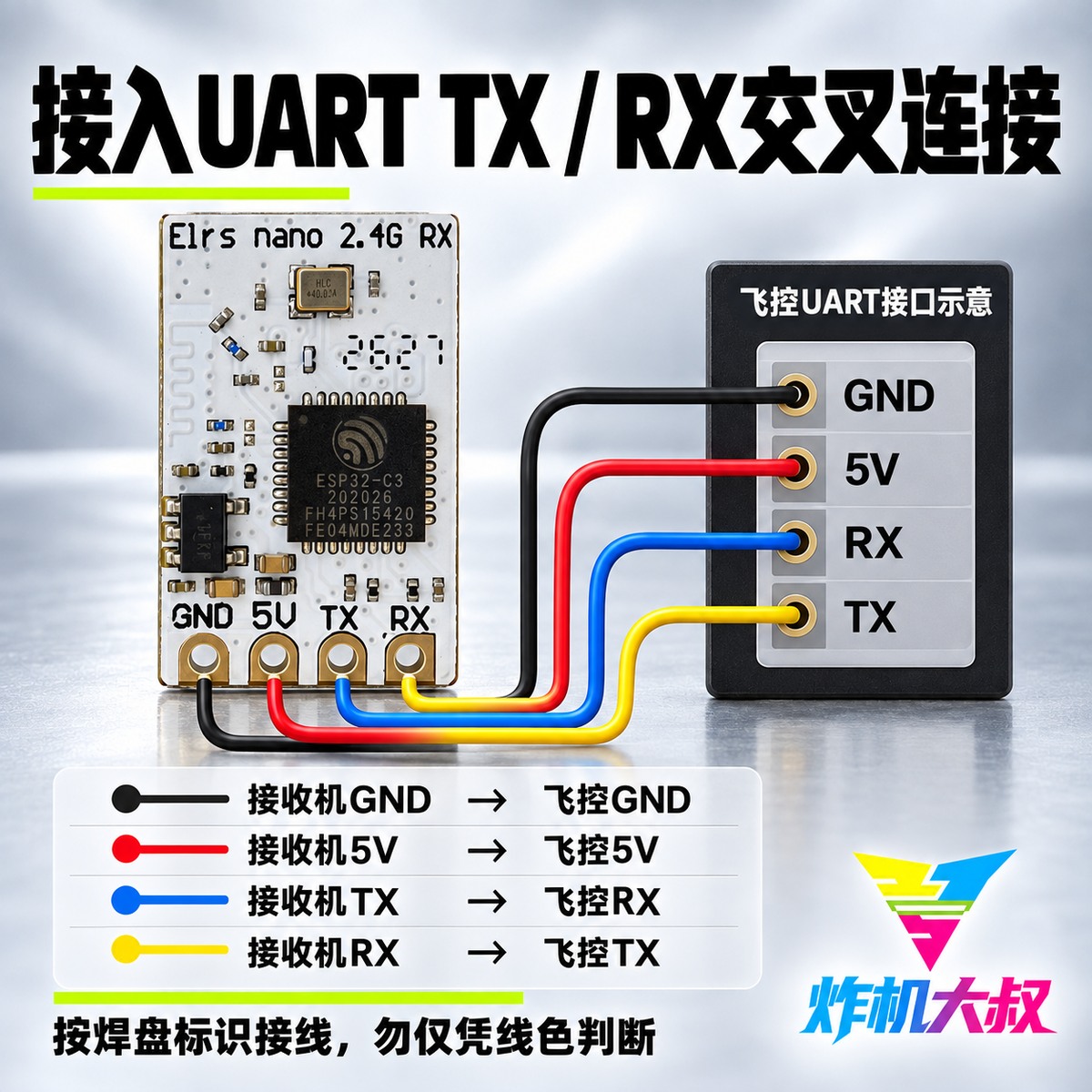
Wire it to the silkscreen
Receiver GND to flight-controller GND, receiver 5V to flight-controller 5V. Receiver TX to flight-controller RX, receiver RX to flight-controller TX, on the same available UART. Check the board silkscreen and the flight-controller manual. Do not guess pins by lead color. Pad left-to-right order looks different on the MCU face and the RF face; do not mix those orientations.
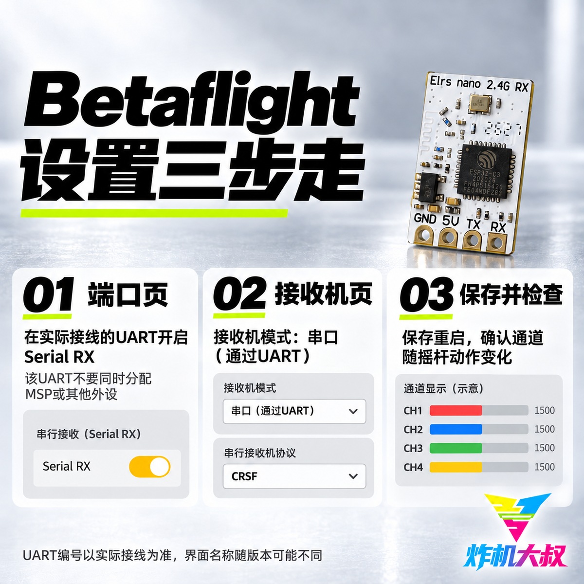
A Betaflight setup example
Enable Serial RX on the UART you actually wired, and do not also assign MSP or another peripheral to that UART. Set the receiver mode to Serial / via UART, protocol CRSF, save, then confirm the channels move with the sticks. The screens in the photo set are a setup illustration; names may differ between software versions. This only demonstrates CRSF. It does not claim that other output protocols are plug-and-play on the factory firmware at the same time.
What is in the box
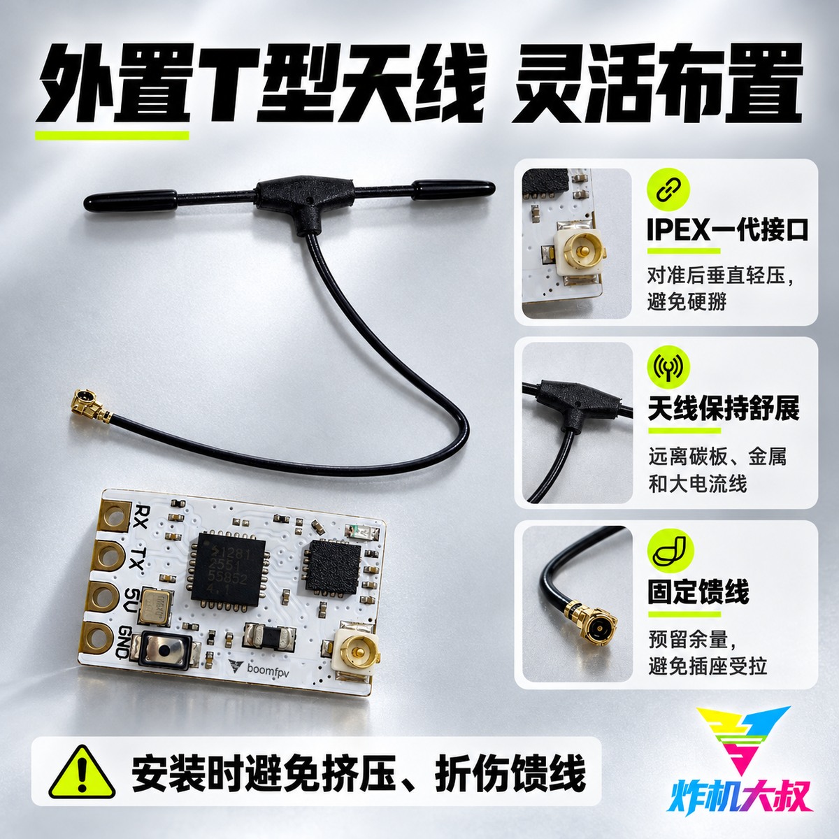
Receiver ×1, mini T-style steel-wire antenna ×1, clear heat-shrink tubing ×2, 4-pin silicone lead 10cm ×1. Align the IPEX connector and press straight down lightly; do not bend it hard. Extend the antenna, keep it away from carbon, metal, and high-current leads, and secure the feed line with some slack.
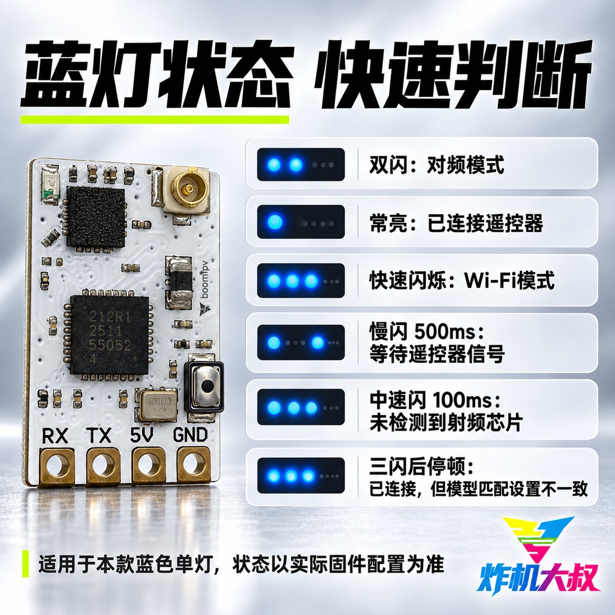
Blue single-LED status
LED reference for this blue single-LED board: a double flash means bind mode; steadily on usually means connected (it may also be in the bootloader — judge from the actual situation); a fast flash is Wi-Fi mode; a 500ms slow flash means waiting to connect; a 100ms mid-speed flash means no RF chip detected; three flashes then a pause means connected but the model-match setting does not agree. Follow the actual firmware and configuration. This is not a promise that the receiver will enter bind on every power-up, or that it will enter Wi-Fi after a fixed time.